 |
 |
|
|
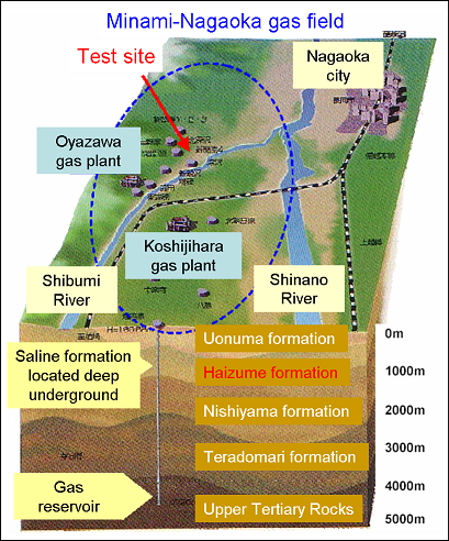
Demonstration Test and Monitoring at the Iwanohara Test Site Purpose Injecting CO2 into an actual aquifer in Japan, data on the CO2 behavior during and after injection was obtained and was used for geotechnical analysis and evaluation. Through this process, understanding was gained on the CO2 storage mechanism. It was also verified that CO2 could be stored securely by using a newly developed long-term behavior prediction simulator. Iwanohara Demonstration Test Site  Progress FY 2000 Selection of the test site, layout of an injection well & observation wells, excavation of Injection Well CO2-1 FY2001 Excavation of Observation Wells CO2-2 and CO2-3, deliberation of a monitoring plan FY2002 Injection well test (ascertaining permeability), simulation study (reviewing the injection rate, etc.), design and construction of an injection facility, excavation of Observation Well CO2-4, preparation of an injection operation plan (review of injection rate, injection layer), update of the monitoring plan, initial monitoring of seismic tomography FY2003 Completion of the excavated injection well (acidic treatment of Injection Well CO2-1), installation of an injection facility, injection operation (injection of 3,977t), monitoring, and simulation study FY2004 Injection operation (completion of 10,405t of injection), monitoring, site restoration work (removal of injection facility), and simulation study FY2005 Monitoring, sampling, and simulation study FY2006 Monitoring and simulation study Description of Injection Demonstration Site Minami-Nagaoka gas field We were permitted temporary use of the Minami-Nagaoka gas field owned by Teikoku Oil for the demonstration test. It is located on the left bank of the Shibumi River, a tributary of the Shinano River system, in the southwestern section of Nagaoka City. Reservoir for injection The selected reservoir is a predominantly sandstone area (thickness: approx. 60m) in the Haizume formation of the Early Pleistocene Epoch which is distributed at a depth of approximately 1,100m. Geology of the reservoir The selected reservoir has a closed anticlinal structure and the test site is located at its southern limb. The reservoir at the test site is monoclinally tilted toward east-northeast at an angle of 15°. Injection zone The reservoir formation is divided roughly into five zones according to lithology (Zone-1 to Zone-5). Of the five zones, Zone-2 (thickness: approx. 12m) having the most favorable permeability was selected as the target injection zone. Geology of the Test Site
 Well layout and monitoring items 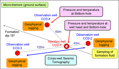 Injection Injection began on July 7, 2003. The injection rate was 20 t/day during FY2003 and 40 t/day during FY 2004. The injection work was completed in January 2005 with the final cumulative injection amount totaling 10,405 tons, without experiencing any serious problems, excluding periodical inspection/repair of the CO2 supply plant (Mar-Apr, 2004), suspension of injection due to CO2 supply shortage (Jul-Aug, 2004), and halt of injection due to the Mid-Niigata Chuetsu Earthquake (Oct. 23-Dec. 6, 2004). Progress of injection
 Click to enlarge Temperature and Pressure Measurements at the Well Bottom Continuous measurements of the temperature and pressure of the target reservoir, Zone-2, were initiated in June 2003 at Injection Well CO2-1 and Observation Well CO2-4 preceding the start of actual injection. Measurements are still being continued even after the injection has ended. This provides basic data on the conditions of the CO2 reservoir. It also provides monitoring so that the reservoir pressure does not exceed the formation breaking pressure (18.6 MPa or higher). Results of pressure measurement
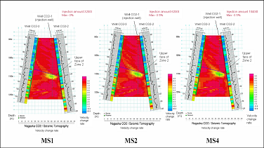
 Click to enlarge Crosswell Seismic Tomography Targeting the area between Observation Wells CO2-2 and CO2-3, seismic wave measurements were performed as follows: 1st measurement before the start of CO2 injection (Feb 2003), 2nd to 5th measurements during injection and immediately after the completion of injection (Jan 2004 - Jan 2005), and the 6th measurement eight months after the completion of injection (MS 6: monitoring survey). The overall image of CO2 distribution in the reservoir was obtained showing an area having a declining seismic wave velocity. With this image, it was confirmed that the CO2 distribution area expanded toward the dip of the formation as the injection work advanced. Results of cross-well seismic tomography (change of P-wave velocity)
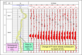
 Click to enlarge Other Monitorings Geophysical logging Reach of CO2 to Observation Wells CO2-2 (Mar 2004) and CO2-4 (June 2004) was confirmed and subsequently the change of physical property values (P-wave velocity, specific resistance, porosity) was monitored. Sampling and analysis of fluids Using the fluid samples, reach of CO2 to Observation Well CO2-2 was confirmed directly. Micro-tremors It was confirmed that no correlation exists between the CO2 injection amount (injection rate, cumulative injection amount) and the occurrence of micro-tremors. Results of geophysical logging (Observation Well CO2-2: change of P-wave velocity subsequent to reach of CO2)
 Click to enlarge Simulation Study GEM-GHG simulator The long-term CO2 behavior prediction simulator called GEM-GHG was developed by adding a CO2 geological storage function to the existing natural gas geological storage simulator (GEM-UGS). CO2 behavior prediction Using an optimal reservoir model derived from history-matching of the monitoring data (change of well bottom pressure, reach time of CO2 to the observation wells), the storage status of injected CO2 as well as its long-term behavior after 1,000 years was predicted. Distribution of dissolved CO2 after 1,000 years
 Impact of the Mid-Niigata Chuetsu Earthquake To identify the impact of this earthquake on the CO2 geological storage, the conditions of the wells, the reservoir, and the injection facility were inspected and tested by various methods. They include comparison of the reservoir status before and after the earthquake by geophysical logging and seismic wave tomography; evaluation of well bottom pressures measured at the time of the earthquake; check of well conditions by cement bond sonic logging and a borehole televiewer; and inspection and air tightness/pressure test of the injection facility. As a result of these tests and inspections, the conditions of the wells, the reservoir, and the facility were found intact even after the earthquake, and the injection was resumed.
Distribution of seismic intensity during the Mid-Niigata Chuetsu Earthquake
 Achievements
|
||||||||||||||||||||||||||||||||||||||||||||||||||||||||||||||||||||||||||||||||||||
|
|||||

|
|